Before we get into the best types of flow meters that are best compatible for hot/chilled water systems, we need to get familiar with what electromagnetic flow meters are, what components make this flow meter well sorted after in the industry and what makes them better than the rest of the competition.

What is an Electromagnetic Flow Meter?
Electromagnetic flow meters for hot/cold water systems, also known as magmeters, are part of the concept of velocity or volumetric flow meters. These devices work in accordance with Faraday’s law of electromagnetic induction, which states that a voltage will be induced when a conductor passes through a magnetic field. Magmeters can only be used to measure conductive fluid flow rates.
Prior Magmeter designs required a fluidic conductivity of between 1 and 5 microsiemens per centimeter to function properly. The necessary threshold has, however, been 100 times lower in modern designs, remaining between 0.05 and 0.1.
What constitutes an Electromagnetic Flow Meter for Hot/Chilled Water Systems?
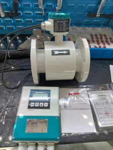
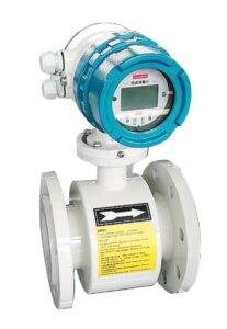
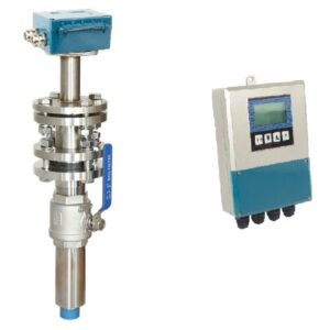
The Electromagnetic Flow Meter for Hot/Chilled Water Systems is constituted of a non-magnetic pipe that is lined with an insulating material. Magnetic coils in paired together are also included and a pairing of electrodes can be found penetrating the pipe and its linings.
Magmeter Excitation
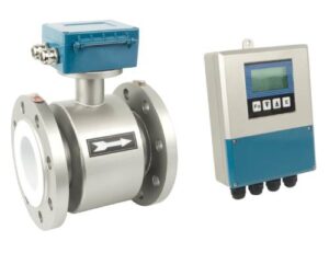
The voltage that is developed at the location which sits the electrodes has been measured to be in millivolt signals. This can be easily converted into a standard current (4 – 20 mA) or into a frequency output of 0 – 10,000 Hz at or in close proximity to the flow tube. With the installation of intelligent magnetic transmitters with digital outputs gives room for direct connection to a distributed control system.
Due to the weakness in strength of the signals generated by the magmeter, the lead wire is shielded (and is advised by manufacturers to be shielded) and twisted if you sort to make the transmitter a remote.
Powering of the magmeter’s coils can be performed through either using alternating or direct currents. During an AC excitation, line voltage is applied to the magnetic coils, this then results in the flow signal becoming more like a sine wave in appearance. The amplitude of the wave is proportional to velocity.
Noise voltages can also be induced in the electrode loop in addition to the flow signal. Out-of-phase noise can be easily filtered, but in-phase noise has the requirement of the stoppage of the flow (with the pipe full) and the transmitter output set to zero.
One main issue with the AC magmeter designs is that the noise can vary with process conditions and frequency re-zeroing is required to maintain accuracy.
In a DC excitation design, a low frequency (7 – 30 Hz) DC pulse is used to stimulate the magnetic coils. When the coils are pulsed on, the transmitter reads both the flow and noise signals. In between pulses, the transmitter only the identifies noise signal. Therefore, the noise can be continuously eliminated after each cycle.
This in turn gives provision for a stable zero which then eliminates zero drift. Added to its ability for accuracy and its ability to measure lower flows. DC meters are considerably less bulky, installed easily, and have lower energy consumption while being cost-efficient that its AC counterpart. Another strong suit is that it uses significantly more power that previous generations and this in turn creates a more powerful flow tube signal.
Flow Tubes, Liners, and Probes
Usually, the flanged flow tube’s lay length dimensions are within the range suggested by the International Organization for Standardization (ISO).
The short form magmeters’ dimensions also follow the ISO recommendations. There is a huge need for magnetic flow tubes and liners, which are produced utilizing a variety of materials that are frequently utilized in all process industries, including the food, pharmaceutical, mining, and metals industries.
It Is crucial to keep in mind that some liner materials, namely PFA, may get hurt if pry bars are utilized during installation or removal from the process piping. They may also be damaged if the flange bolts are overtorqued during installation. There are liner protectors available to aid in the avoidance of such circumstances.
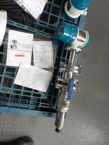
Magnetic flowmeters can be package as probes and inserted into process pipes through taps. Electrodes and magnetic coils are inserted into the process pipes using these probes which reflects the velocity of the probe tip and not the average fluid velocity across the pipe.
Electrodes
The electrodes and process fluid are in close proximity in more traditional flow tubes. If they are created by a droplet of liquid platinum that sinters through ceramic lining and fuses with aluminum oxide to make a flawless seal, they may be removable or permanent. In comparison to other designs, this one is more sought-after due to its affordability, resilience to abrasion and wear, insensitivity to nuclear radiation, and suitability for hygienic applications due to the absence of voids where bacteria can hide and grow.
On the other hand, the ceramic is unable to withstand bending, strain, or abrupt cooling while being insensitive to oxidizing acids or hot, concentrated caustic.

Electromagnetic Flow Meter for Hot/Chilled Water
The volumetric flow meter Electromagnetic Flow Meters, sometimes referred to as Mag Flow Meters, is suited for usage in waste water applications and other situations requiring proper liquid conductivity and low pressure drop.
There are no moving parts in the gadget, and it is incompatible with distilled water and hydrocarbons. Mag flow meters are also simple to keep up with.
Principle of Magnetic Flow Meter Based on Faraday’s Law
Magnetic flow meters function according to Faraday’s Law of Electromagnetic Induction. According to this theory, a voltage E produced when a conductive medium flows through a magnetic field B is proportional to the medium’s speed (v), the magnetic field’s density (d), and the conductor’s length (l).
The energy passing via wire coils inside or outside the meter’s body produces the magnetic field of a magnetic flow meter. The liquid inside the pipe acts as a conductor and generates a voltage proportionate to the average flow rate.
This voltage is detected by sensing electrodes built into the Magflow meter’s body, and it is then transferred to a transmitter, which calculates the volumetric flow using the pipe dimensions.
Mathematically, Faraday’s law can be written as E is proportional to V x B x L, where E is the voltage generated in the conductor, V is its speed, B is the strength of the magnetic field, and L is its length.
It is essential that the liquid flow that the magnetic flow meter will measure is electrically conductive. Faraday’s Law states that the average liquid velocity (V), conductor length (D), and magnetic field intensity (B) all have an impact on the signal voltage. Thus, the cross-section of the tube will produce the magnetic field.
In essence, when the conductive liquid travels through the magnetic field, voltage is induced. This generated voltage, which is inversely proportional to the liquid flow rate, is measured using two stainless steel electrodes positioned in opposition to one another.
The flow meter’s two electrodes are connected to an advanced electronic circuit that can further process the signal. After being processed, the signal is sent to the microprocessor that calculates the liquid’s volumetric flow.
Formula for Electromagnetic Flow Meters.
To measure flow, electromagnetic flow meters employ Faraday’s law of electromagnetic induction. According to Faraday’s law, anytime a conductor of length “l” moves at a speed “v” perpendicular to a magnetic field “B,” an emf “e” is induced in a direction that is mutually perpendicular and is given by
Where B is the magnetic flux density (Wb/m2),
e = Blv… (eq1)
L = conductor length (m) and
v = conductor velocity (m/s).
Given by, is the volume flow rate Q.
Where d is the pipe’s diameter and v is the average flow speed (in this case, conductor velocity), Q is defined as (d2/4) v… (eq2).
Using (eq1) as an example
V = e/Bl
Q = πd2e/4Bl
Q is equal to K, where K is the meter constant.
As a result, the volume flow rate and the induced emf are related. In practical applications, we must enter the magnetic flow meter’s “K” value, which can be found in the vendor’s catalog or manual.

Limitations of electromagnetic flow meters
(i) the requirement that the substance being measured be conductible. As a result, it cannot be used to measure the flow rate of gases, steam, petroleum products, or other liquids with extremely low conductivities.
(ii) The effective resistance of the liquid between the electrodes should not be higher than 1% of the impedance of the external circuit in order to make the meter insensitive to changes in liquid resistance.
(III) It is quite an expensive device.
(iv) The volume of any suspended matter in the liquid will be taken into account because the meter always measures volume rate.
(v) When the flow tube is fitted in a horizontal pipeline, the electrodes should be on the horizontal diameter to prevent any problems brought on by entrained air.
(vi) Isolating valves are necessary, and it can also be necessary to have a bypass so that the flow can be diverted during a zero check, as a zero check on the installation can only be done by stopping the flow. If regulating valves are set upstream of the meter, the pipe must run full.